
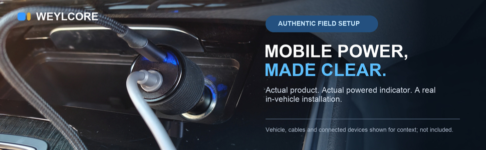
The field insight
Boosting to 30V before the long cable is the key move. At the same 60W, an ideal 12V path carries about 5A; a 30V path carries about 2A. Lower downstream current means less cable loss—but the vehicle socket and adapter input still carry the heavier current.
30V creates headroom; it does not create power
Starlink lists Mini at an average power consumption of 25 to 40 watts and specifies a 12 to 48V input with a 60W rating. For its USB-C accessory path, Starlink calls for a 100W USB Power Delivery source capable of 20V/5A. ↗
A boost converter moves the downstream cable to a higher voltage. For equal power, that lowers cable current; because resistive loss follows I²R, the benefit becomes more important as the run gets longer. Conversion is not free, however, and the source outlet still sets the total power ceiling.
| 60W path | Ideal current | What it means |
|---|---|---|
| 12V input side | 5A | Higher burden on socket, plug, fuse, and vehicle wiring |
| 30V downstream side | 2A | Lower cable current and lower same-cable I²R loss |
Those are ideal first-principles values. A real converter draws more input power than it delivers because conversion has losses. The point is not that 30V creates extra energy; it moves the long cable to a lower-current operating point.
The low-voltage side works harder
WEYLCORE bench data makes the input-side tradeoff visible. The same 5 m setup was observed at approximately 60W output and 21°C ambient:
| Input | Input current | Output | Peak recorded temperature |
|---|---|---|---|
| 12.0V | 5.83A | 30.0V / 60.3W | 41°C |
| 13.2V | 5.17A | 30.0V / 60.4W | 33°C |
| 14.8V | 4.607A | 30.0V / 60.4W | 33°C |
The 12.0V condition required about 27% more input current than the 14.8V condition for nearly the same delivered load. The recorded temperature was also higher in that run.
This is the practical surprise: the cable after the converter benefits from 30V, while the socket, plug contacts, fuse, and vehicle wiring before it still face the high-current burden. A loose or worn outlet contact can therefore become the weak point even when the adapter itself is well designed.
What over-temperature protection can—and cannot—do
The current WEYLCORE product specification lists over-temperature protection. A useful implementation needs three pieces: a temperature signal, a trip or limit threshold, and an intervention such as reducing or shutting down output. A housing that merely tolerates warmth is not the same thing.
Our present bench record did not intentionally force a protection event. It shows operating temperature under the stated conditions, but it does not verify a cutoff temperature, trip accuracy, or recovery sequence. We do not publish numbers the test did not establish.
An internal sensor also cannot see every hot spot. Heat concentrated at a worn socket contact may sit outside the adapter housing. Unusual heat at the plug, outlet, cable, or adapter means disconnect and inspect the entire path.
The thermal aha
The hottest failure point may be upstream of the temperature sensor. Internal protection cannot repair a loose vehicle socket.
30V does not erase cable loss
Voltage drop still grows with current, resistance, and distance. Longer or thinner cable consumes more of the headroom the converter created. Startup and changing network load may expose a marginal path that looked fine at idle.
A practical rule is to buy placement first and cable length second: use 3 m for a compact route, 5 m when the Mini needs room around a vehicle, and 10 m only when the clear-sky location truly requires the separation.
Two output labels do not create two power budgets
The dedicated DC path and the auxiliary USB-C port share the same source, converter, and thermal environment. Their standalone maximum labels are not automatically additive. The usable combined load is limited by the lowest-rated element in the path: vehicle outlet and fuse, plug contact, adapter, cable, or connected device.
This explains a common surprise: adding a fast-charging phone can disturb a Mini setup that was stable by itself. The new load did not change the printed ratings; it consumed current and thermal margin that the first load was already using.
Three checks before a trip
- Source: confirm outlet voltage, fuse rating, ignition behavior, and a firm plug fit.
- Path: use the shortest practical cable; keep every junction dry, supported, and out of door gaps.
- Load: run the Mini under real use, then check the plug, outlet, adapter, and cable for looseness or unusual heat.
Parked use is a battery decision
An outlet may switch off with the ignition, stay live, or behave differently during engine start. Check the actual outlet; dashboard and cargo sockets may not share the same fuse or behavior.
If the starter battery is the source, preserve restart reserve. Longer parked use belongs on a suitable monitored auxiliary power system.
Where the WEYLCORE Car Power Adapter fits
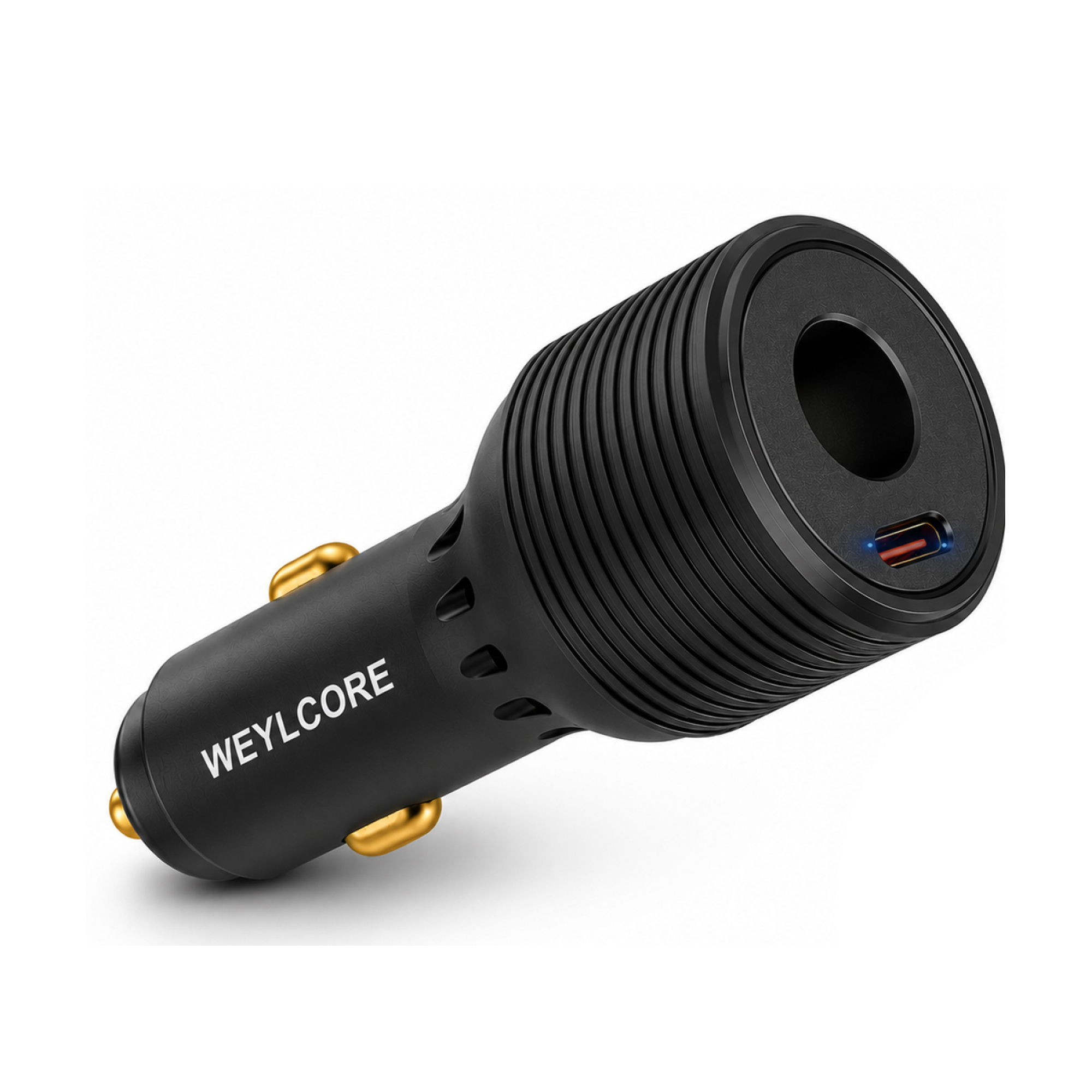
The WEYLCORE adapter boosts the dedicated DC path to 30V before the downstream Mini cable. The separate USB-C port is for a verified phone or low-power accessory; it is not a second Mini output.
Both outputs still share the vehicle source and the adapter's thermal budget. Their maximum labels are not automatically additive. The adapter is sold without a Mini cable, so pair it with only the length your placement needs.
The product page lists the exact output roles and package boundary. The Mini cable is separate so the route can determine the length.
Read the symptom backward
| What you see | Likely boundary | First check |
|---|---|---|
| Restarts only under demand | Voltage or current margin | Outlet, long cable, and every contact |
| Plug is hot; housing is not | Socket contact resistance | Stop; inspect fit, wear, debris, and damage |
| Stable alone; unstable with phone | Shared input or thermal budget | Remove the auxiliary load and re-test |
| Works driving, fails parked | Outlet voltage or battery behavior | Measure the actual source state |
| USB-C source will not start Mini | Wrong PD profile | Verify 100W USB PD with 20V/5A capability |
Evidence and limits
The Mini requirements are from Starlink's specification. The conversion figures above come from one WEYLCORE engineering workbook using a 5 m path, approximately 60W loads, 21°C ambient, and 45–50 minute observations. The temperature-sensor location was not recorded, so the values must not be described as enclosure, connector, or PCB temperature. This is useful bench evidence, not a certification report or proof of every vehicle, ambient condition, production lot, or protection-trip threshold.
Continue planning
Need a USB-C-to-DC handoff? Read the Adapter Kit guide. Choosing a portable support? Read the tripod placement guide.
Safety and compatibility note: Vehicle electrical systems vary. Follow the vehicle, Starlink, and accessory instructions. Disconnect equipment that is damaged, loose, wet where it should remain dry, or unusually hot. WEYLCORE is an independent accessory brand and is not affiliated with, endorsed by, or sponsored by Starlink or SpaceX. Starlink is a trademark of Space Exploration Technologies Corp.