60-second summary
- Source: confirm voltage and the exact USB-C PD profile.
- Long run: choose enough conductor size to preserve voltage margin.
- Connections: support the USB-C end and protect the Mini-side joint from weather and strain.
- Protection: verify reverse-current behavior for the exact adapter revision.
What the complete power path must do
Compatibility begins with source voltage, USB-C PD profile, and connector fit. These checks are necessary, but they do not prove that the complete path will remain stable.
Stability also depends on cable resistance, connector strain, environmental exposure, and where conversion and protection occur.
The practical test is simple: can the path deliver the required power at the actual source voltage and cable length without restarts, hot contacts, or stressed connectors?
Three rules for a reliable setup
- Split conversion from delivery. The input conversion or negotiation stage and the long power cable serve different functions.
- Put the thicker wire where distance matters. Conductor resistance consumes more voltage margin as cable length increases.
- Protect the USB-C end and the Mini-side connection differently. These interfaces have distinct electrical, mechanical, and environmental stress modes.
Starlink Mini power is a system-design problem, not an isolated cable-selection problem.
Specifications show compatibility. The system determines stability.
Official requirements establish the baseline. Starlink says Mini supports 12-48V DC input, and for the official USB-C path it calls for 100W USB-PD at 20V/5A. ↗ ↗
Starlink's own Mini accessories guide also lists both a Mini USB-C cable and a Mini Car Adapter built around that same 100W requirement. ↗
USB-C PD is a practical Mini power option for portable use, battery systems, and mobile setups. Direct DC may be more appropriate in van, RV, marine, or fixed installations where the source and wiring are already designed around DC distribution.
Reliability problems often arise from interactions among source capability, conversion, cable resistance, and connector quality rather than from a single nominal voltage value.
That system has four parts:
- the power source
- the input adapter or conversion stage
- the long power cable
- the Mini-side outdoor connection
An under-specified component in any one stage reduces the stability margin of the complete system.
A stable power path has four stages
Power source -> input adapter (USB-C or DC) -> flexible 16AWG long power cable -> protected Mini-side connection -> Mini
Keep conversion short; let the long cable carry power
A single long, all-in-one cable must combine compact connector packaging, power negotiation or conversion, mechanical support, and low-resistance delivery. Separating these functions reduces conflicting design requirements.
The system has two primary jobs:
- the input adapter has to handle negotiation, conversion, or protection
- the long power cable has to carry power with less voltage loss
This architecture assigns conversion and protection to a short, serviceable input section while the long cable is optimized for power delivery and routing.
Choose cable gauge for the full run
Cable resistance produces voltage drop and I²R heating. Longer runs increase both effects for a given conductor size and load.
The long power-delivery section uses 16AWG conductors to preserve more voltage margin over distance. The choice is driven by resistance over the required run, not by gauge as an isolated specification.
A smaller-gauge cable is not automatically unsuitable; suitability depends on length, current, source voltage, connector resistance, and allowable voltage drop. The practical constraint is that operating margin decreases as cable length and load transients increase.
Why a split power path works
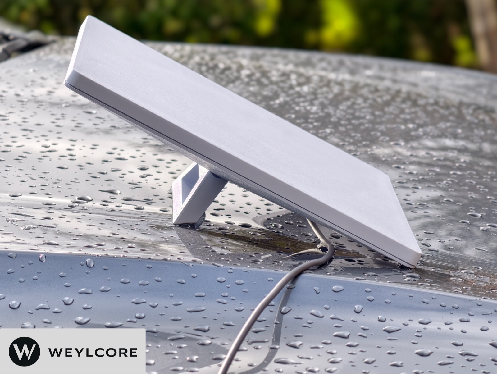
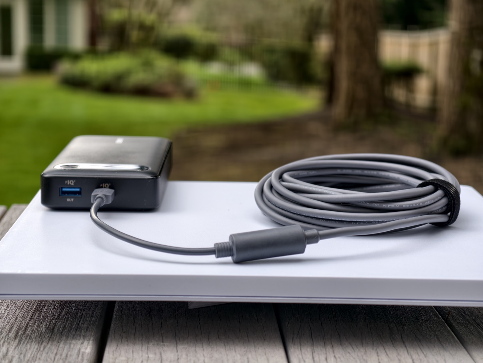
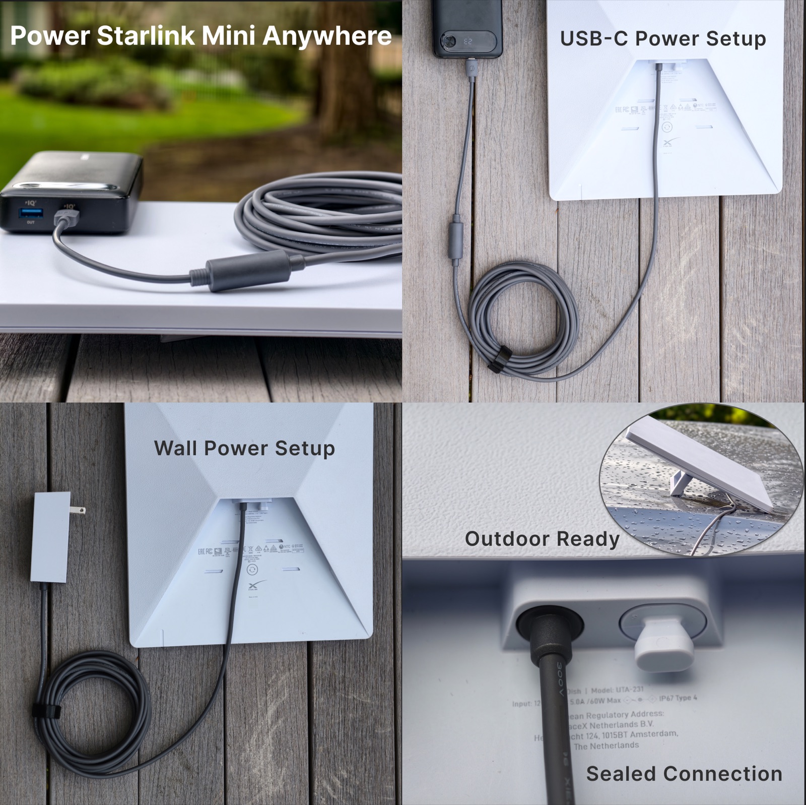
The Weylcore Starlink Mini Cable Kit on Amazon is built around three parts:
- a short USB-C PD to DC adapter section
- a 5 m 16AWG DC cable
- a Mini-side connector with a protective shell
The defining architecture is a modular split power path.
Conductor size also introduces a mechanical tradeoff.
Larger conductors are typically less flexible, which can make a cable more difficult to route, coil, and strain-relieve in a vehicle or outdoor installation.
Gauge alone therefore does not define cable quality. The design objective is sufficiently low resistance for the run while retaining practical flexibility and connector strain relief.
Keep the USB-C segment short
USB-C is convenient, but it is still a compact consumer connector. It has to handle power negotiation, internal electronics, and repeated plugging and unplugging.
USB-C is not the only valid Mini power path. It is the path that requires the most attention to negotiation electronics, compact termination, and repeated connection cycles in portable setups.
This is a practical design constraint. In USB-C cable design, the e-marker or EMCA electronics live inside the connector housing itself, and higher-power or full-featured cable designs may put those electronics in one plug or even both plugs. ↗ ↗
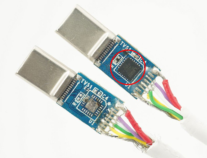
Larger conductors help reduce voltage drop over long runs, but the USB-C connector still has limited internal volume, compact electronics, and small termination points. It should not carry the full mechanical load of a long, heavy cable.
The conductor size that reduces loss over distance is also more difficult to package, terminate, and strain-relieve inside a compact USB-C connector.
Combining long-distance delivery and USB-C termination in one cable increases stiffness, connector bulk, termination difficulty, and mechanical load at the USB-C interface.
A short USB-C adapter section paired with a heavier long cable limits mechanical load on the compact interface and keeps the conversion section serviceable. The longer section can then focus on lower-loss power delivery.
Protect the Mini-side connection outdoors
In many field installations, the Mini-side connection is the most environmentally exposed part of the power path.
This interface must account for rain, dust, movement, repeated setup, and vibration in vehicle or portable use.
Environmental suitability must therefore be evaluated at the connector, not inferred from the electrical specification alone.
Verify reverse-current behavior; do not assume it
USB-C PD negotiation and reverse-current blocking are separate functions. Successful negotiation establishes what the source may deliver; it does not establish whether voltage already present on the DC side can drive current back toward the USB-C source.
Unintended reverse current can damage conversion electronics. Do not energize the same path from both ends, and do not infer reverse-current protection from a PD label or protection icon.
A credible protection claim should identify the exact hardware revision, test direction and voltage, measured blocking or leakage behavior, and the resulting device response.
See the USB-C-to-DC reverse-current guide for the distinction among PD negotiation, reverse current, and reverse polarity.
A modular path is easier to service
Locating conversion electronics in the short adapter section limits the replacement scope when the source changes or the compact connector section reaches the end of its service life.
This reduces replacement cost and supports future source or adapter changes.
What to check before you connect
- The input path matches the intended source: portable USB-C PD or direct DC.
- Conductor size and cable length preserve adequate voltage margin while retaining practical flexibility.
- The Mini-side connection is appropriate for the expected exposure and mechanical strain.
- Protection claims for the conversion stage are supported by evidence for the exact hardware revision.
Choose the cable length your placement needs
WEYLCORE now offers the same 16AWG cable-kit architecture in three lengths. Use the shortest practical run that reaches your planned Mini location without tension.
Compare the WEYLCORE 3 m, 5 m and 10 m cable kits for the reach your placement needs. For a connector handoff rather than a full cable run, see the Starlink Mini 3-in-1 Adapter Kit.
Vehicle-power planning
See the Starlink Mini car and RV power guide to understand 30V boost conversion, vehicle-socket current, thermal limits, and a practical setup checklist.
What to remember
If the Mini restarts, check the path in order: source profile, adapter, voltage at the far end of the long cable, connector fit, and temperature. Swapping parts at random can hide the cause.
For a long run, 16AWG conductors help preserve voltage margin. At the USB-C end, keep the compact negotiation and conversion section short. At the Mini end, protect the connection from water and cable pull.
Use the shortest cable that reaches without tension, then test the complete setup under real load before relying on it in the field.